Alle technischen Informationen, Maße und Daten zu LFD-Gelenklagern, Gelenkköpfen, Gelenklagertechnik - Datenbank der LFD Wälzlager GmbH.
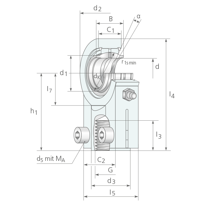
HYDRAULIK-GELENKKOPF klemmbar DIN ISO 8132
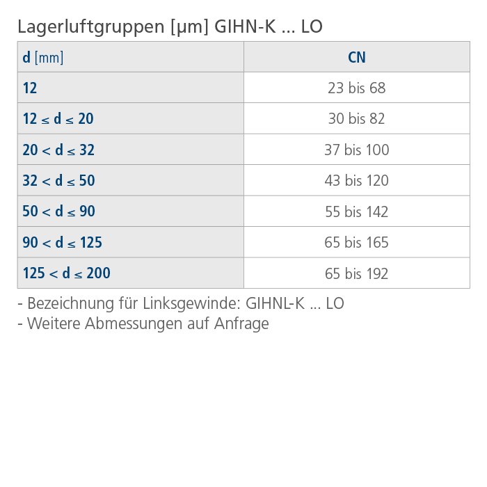
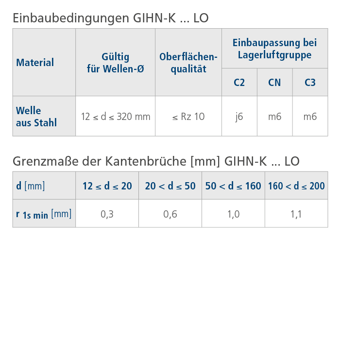
Gleitpaarung: Stahl/Stahl >> wartungspflichtig GIHN-K ... LO
Hauptabmessungen | Masse | Tragzahlen | ||||||||||||||||||
d | B | C1 max | dK | ≈ α | m | C | C0 | ≈ d1 | G | d2 max | d3 max | h1 | I3 min | I4 max | I5 max | I7 min | C2 max | d5 1) | MA | |
[mm] | [mm] | [mm] | [mm] | [°] | [kg] | [kN] | [kN] | [mm] | [-] | [mm] | [mm] | [mm] | [mm] | [mm] | [mm] | [mm] | [mm] | [-] | [Nm] | |
|
GIHN-K 12 LO*) |
12 |
12 |
11 |
18,0 |
4 |
0,10 |
10,8 |
24,5 |
15,5 |
M 12 x 1,25 |
33 |
17,0 |
38 |
17 |
55,5 |
32 |
14 |
10,6 |
M 5 x 16 |
6 |
|
GIHN-K 16 LO |
16 |
16 |
13 |
23,0 |
4 |
0,21 |
17,6 |
36,5 |
20,0 |
M 14 x 1,5 |
32 |
22,5 |
44 |
19 |
64,5 |
40 |
18 |
13,0 |
M 6 x 14 |
10 |
|
GIHN-K 20 LO |
20 |
20 |
17 |
29,0 |
4 |
0,35 |
30,0 |
48,0 |
25,0 |
M 16 x 1,5 |
40 |
26,5 |
52 |
23 |
77,5 |
47 |
22 |
17,0 |
M 8 x 20 |
25 |
|
GIHN-K 25 LO |
25 |
25 |
21 |
35,5 |
4 |
0,65 |
48,0 |
78,0 |
30,5 |
M 20 x 1,5 |
47 |
32,0 |
65 |
29 |
97,0 |
54 |
27 |
17,0 |
M 8 x 20 |
25 |
|
GIHN-K 32 LO |
32 |
32 |
27 |
44,0 |
4 |
1,20 |
67,0 |
114,0 |
38,0 |
M 27 x 2,0 |
58 |
40,0 |
80 |
37 |
120,0 |
66 |
32 |
22,0 |
M 10 x 25 |
49 |
|
GIHN-K 40 LO |
40 |
40 |
32 |
53,0 |
4 |
2,00 |
100,0 |
204,0 |
46,0 |
M 33 x 2,0 |
70 |
49,0 |
97 |
46 |
147,0 |
80 |
41 |
26,0 |
M 10 x 30 |
49 |
|
GIHN-K 50 LO |
50 |
50 |
40 |
66,0 |
4 |
3,75 |
156,0 |
310,0 |
57,0 |
M 42 x 2,0 |
89 |
60,5 |
120 |
57 |
181,0 |
96 |
50 |
32,0 |
M 12 x 35 |
86 |
|
GIHN-K 63 LO |
63 |
63 |
52 |
83,0 |
4 |
7,25 |
255,0 |
430,0 |
71,5 |
M 48 x 2,0 |
108 |
72,5 |
140 |
64 |
213,0 |
114 |
62 |
38,0 |
M 16 x 40 |
210 |
|
GIHN-K 70 LO 2) |
70 |
70 |
57 |
92,0 |
4 |
11,05 |
315,0 |
540,0 |
79,0 |
M 56 x 2,0 |
132 |
83,0 |
160 |
76 |
247,0 |
135 |
70 |
42,0 |
M 16 x 40 |
210 |
|
GIHN-K 80 LO |
80 |
80 |
66 |
105,0 |
4 |
15,15 |
400,0 |
605,0 |
91,0 |
M 64 x 3,0 |
155 |
93,0 |
180 |
86 |
272,0 |
148 |
78 |
48,0 |
M 20 x 50 |
410 |
|
GIHN-K 90 LO 2) |
90 |
90 |
72 |
115,0 |
4 |
19,70 |
490,0 |
750,0 |
99,0 |
M 72 x 3,0 |
168 |
103,5 |
195 |
91 |
298,0 |
160 |
85 |
52,0 |
M 20 x 60 |
410 |
|
GIHN-K 100 LO |
100 |
100 |
84 |
130,0 |
4 |
25,50 |
610,0 |
1060,0 |
113,0 |
M 80 x 3,0 |
185 |
114,0 |
210 |
96 |
324,0 |
178 |
98 |
62,0 |
M 24 x 60 |
710 |
|
GIHN-K 110 LO 2) |
110 |
110 |
88 |
140,0 |
4 |
32,50 |
655,0 |
1200,0 |
124,0 |
M 90 x 3,0 |
210 |
129,0 |
235 |
106 |
366,0 |
190 |
105 |
62,0 |
M 24 x 60 |
710 |
|
GIHN-K 125 LO |
125 |
125 |
102 |
160,0 |
4 |
46,00 |
950,0 |
1430,0 |
138,0 |
M 100 x 3,0 |
262 |
139,0 |
260 |
113 |
407,0 |
200 |
120 |
72,0 |
M 24 x 70 |
710 |
|
GIHN-K 160 LO |
160 |
160 |
130 |
200,0 |
4 |
82,50 |
1370,0 |
2200,0 |
177,0 |
M 125 x 4,0 |
326 |
170,0 |
310 |
126 |
490,0 |
250 |
150 |
82,0 |
M 24 x 80 |
710 |
|
GIHN-K 200 LO |
200 |
200 |
162 |
250,0 |
4 |
168,00 |
2120,0 |
3650,0 |
221,0 |
M 160 x 4,0 |
418 |
221,0 |
390 |
161 |
623,0 |
320 |
195 |
102,0 |
M 30 x 100 |
1500 |